فئات

How Do You Select Safe Clearance Distance for High-Voltage Enclosed Busway?

Safe clearance distance for high-voltage enclosed busway must be selected according to the rated voltage class of the connection — ranging roughly from 75mm at 3.15kV to 300mm at 35kV — because insufficient spacing between phases and enclosure walls directly increases the risk of flashover and equipment failure.
Jul 27th,2026 2 الآراء

Safe clearance distance for high-voltage enclosed busway must be selected according to the rated voltage class of the connection — ranging roughly from 75mm at 3.15kV to 300mm at 35kV — because insufficient spacing between phases and enclosure walls directly increases the risk of flashover and equipment failure.

At ZHERUTONG, we get a surprising number of inquiries that start with a current rating and an installation photo, but never mention clearance distance at all. That's a problem, because picking the wrong clearance is far more expensive to fix than picking the wrong ampacity. A busway with too little current capacity just runs hotter than expected — annoying, but survivable in the short term. A busway with too little clearance can flash over during a switching transient, and by the time anyone notices, there's arc damage, a production stoppage, and a very uncomfortable conversation with the client's electrical inspector.

This guide walks through how we actually think about clearance selection during project review, especially for transformer and generator interconnection work where the stakes are highest. We'll cover the difference between clearance and creepage, how to read voltage-to-clearance tables correctly, how insulation level selection ties into the same decision, and what tends to go wrong at transformer connection points specifically. By the end, engineers and procurement teams should be able to look at a single-line diagram and know roughly what clearance figure they're targeting before a manufacturer even gets involved.

What Is Safe Clearance Distance and Why Does It Matter?

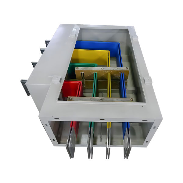
Safe clearance distance is the minimum physical air gap between energized conductors and grounded enclosure surfaces required to prevent dielectric breakdown under normal and transient overvoltage conditions.

Air is actually a decent insulator, up to a point. Beyond that point — determined by voltage magnitude, waveform, and the condition of the air itself — it ionizes and becomes conductive, which is exactly what happens during a flashover. Clearance distance is the design margin that keeps normal operating voltage and expected transient spikes (from switching operations or lightning-induced surges) safely below that ionization threshold.

This is different from simply meeting a dielectric withstand test on paper. Real installations deal with altitude (air density drops as elevation rises, reducing its insulating strength), pollution degree (dust, moisture, and conductive particulates lower effective withstand), and humidity swings that most catalog numbers don't explicitly account for. The baseline clearance figures most manufacturers publish — including the ones we use for RTGM high-voltage enclosed busway — are derived from established methodology referenced in standards such as IEC 60071 and the corresponding GB busway standards, which define insulation coordination principles for extra allowances at higher altitude or contamination levels.

The reason a lot of red-ocean spec sheets simply list a number without context is that most buyers never ask why the number is what it is. That's a mistake. Understanding the engineering logic behind a clearance figure is what lets you correctly judge whether a project's specific conditions call for something above the catalog minimum.

Is Clearance Distance the Same as Creepage Distance?

No — clearance is the shortest air-path distance, while creepage is the shortest distance measured along an insulating surface, and both must be evaluated separately during busway selection.

Clearance is a straight-line air gap; creepage follows the contour of an insulator's surface, which is often longer and more convoluted than the straight-line distance because surface contamination and moisture create alternate conductive paths along solid insulation. A busway design might satisfy clearance requirements comfortably while falling short on creepage if surface materials, coatings, or humidity exposure aren't factored in — this is one of the most common under-specification errors we see in early-stage project drawings, particularly in coastal or high-humidity applications.

How Do You Match Clearance Distance to Voltage Class (3.15kV–35kV)?

Each voltage class from 3.15kV to 35kV has a corresponding minimum safe clearance distance — 75mm, 100mm, 125mm, 150mm, 180mm, and 300mm respectively — and selecting below these thresholds compromises insulation safety margins regardless of enclosure quality.

This table is the core reference point for most of the selection conversations we have with engineers and OEM buyers:

Rated Voltage

Safe Clearance Distance

Engineering Note

3.15kV

75mm

Common for auxiliary transformer taps and smaller distribution loops

6.3kV

100mm

Typical for mid-size industrial substations

10.5kV

125mm

One of the most frequently specified classes for plant-level transformer connections

15kV

150mm

Common step-up for larger industrial or utility-adjacent installations

20kV

180mm

Upper range of standard medium-voltage plant distribution

35kV

300mm

Sharp increase reflecting nonlinear insulation stress at this class

If a system's rated voltage falls between two listed classes — say, a project specifying 13.8kV rather than 15kV — the practical approach is to round up to the next listed class rather than interpolate downward. Clearance is a safety margin, not a linear scaling exercise, and rounding down to save enclosure space is exactly the kind of shortcut that shows up as a field problem later.

One thing worth noting from our own project review process: we don't treat this table as a lookup-and-done exercise. When a drawing comes in specifying, say, a 15kV connection, our engineers cross-check the requested clearance against the actual physical enclosure dimensions, routing path, and support spacing in the layout — because a table value assumes ideal conditions, and actual installations rarely match ideal conditions perfectly. A tight equipment room, an unusually short run between transformer and switchgear, or a support bracket positioned too close to a bend can all erode the effective clearance that looked fine on paper.

Why Does Clearance Increase Sharply Above 20kV?

Clearance requirements rise disproportionately above 20kV because dielectric stress and switching overvoltage risk grow non-linearly with rated voltage, requiring wider safety margins to maintain the same insulation reliability.

The jump from 180mm at 20kV to 300mm at 35kV — nearly double, compared to more incremental steps at lower voltage classes — reflects how insulation coordination margins compound as system voltage rises. Switching transients and lightning-induced surges scale faster than the nominal voltage itself, so the safety buffer has to scale faster too. For panel and equipment room layout planning, this means 35kV installations typically need meaningfully more physical space around busway runs than a simple linear extrapolation from lower voltage classes would suggest — a detail that catches some first-time 35kV buyers off guard during layout planning.

How Does Insulation Level Selection Affect Clearance Requirements?

Insulation level — determined by rated voltage class and expected impulse withstand voltage — sets the baseline that clearance distance must satisfy, meaning the two specifications must always be selected together rather than independently.

This is where the secondary consideration of high-voltage enclosed busway insulation level selection by voltage class 3.15kV to 35kV comes directly into play. Clearance distance answers the question of physical air-gap spacing; insulation level answers the question of how much voltage stress the insulating materials and coordination scheme are designed to withstand, including rated withstand voltage and impulse (lightning-type) withstand voltage. The two figures are paired references, not independent choices — selecting a wide clearance with a mismatched insulation level (or vice versa) undermines the overall safety margin the system is supposed to provide.

Across the 3.15kV to 35kV range, insulation level reference tables typically define both a rated (power-frequency) withstand voltage and a higher impulse withstand voltage figure for each class, since transient surges require a larger instantaneous margin than steady-state operation. In practical terms, this is why manufacturers publish insulation level tables alongside clearance tables rather than treating them as separate documents — a 10.5kV system's clearance figure only makes sense in the context of the impulse withstand rating it's paired with.

Materials matter here too. Epoxy coatings and polyester film insulation are common choices for busway conductor insulation, and their dielectric strength directly factors into how much margin exists beyond the theoretical minimum. Epoxy systems generally offer strong mechanical durability alongside dielectric performance, which is part of why they're widely used in higher voltage class configurations where both electrical and mechanical stress need to be managed together.

Indoor and outdoor installations also require different insulation coordination thinking. Outdoor busway is exposed to weather-driven contamination and moisture cycling that indoor equipment rooms simply don't experience, so insulation coordination for outdoor runs often needs to account for a lower effective withstand margin under wet or polluted conditions, even when the base insulation level rating is identical to an indoor-rated equivalent.

Should Clearance Be Increased for Humid or Corrosive Environments?

Yes — coastal, humid, or chemically corrosive environments often justify clearance and creepage margins above the standard minimum because contamination and moisture reduce effective dielectric strength over time.

Textile plants with airborne fiber and moisture, coastal facilities exposed to salt-laden air, and chemical processing environments are the recurring examples where standard clearance tables shouldn't be treated as the final word. In these settings, we generally recommend a direct conversation with the manufacturer about environment-adjusted specifications rather than defaulting to catalog minimums, since the degradation mechanisms at play are gradual and easy to underestimate during initial design.

How Should You Select Clearance for Transformer and Generator Connections?

Transformer and generator connection points demand extra scrutiny on clearance distance because mechanical vibration, thermal cycling, and short-circuit electromagnetic forces at these junctions can gradually reduce effective spacing if the initial design margin is too tight.

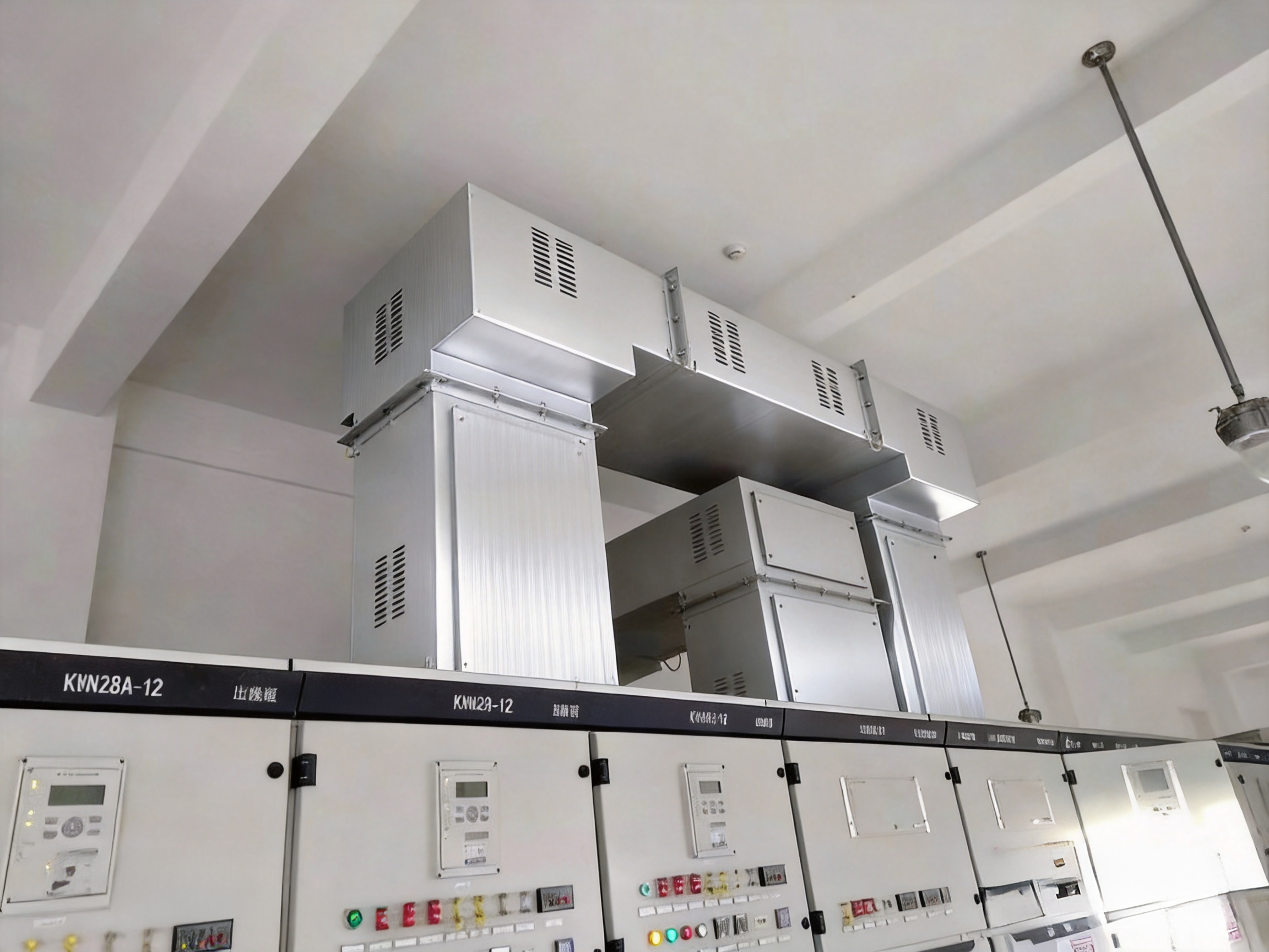
Transformer and generator interconnection points are where clearance selection stops being a purely electrical calculation and becomes a mechanical-and-electrical combined problem. Consider a typical scenario: connecting enclosed busway from a 10.5kV transformer secondary to a distribution assembly. On paper, the 125mm clearance figure for 10.5kV applies cleanly. In practice, the connection point experiences continuous low-level vibration from the transformer, thermal expansion and contraction as load cycles through the day, and — in the event of a downstream fault — significant electromagnetic force from short-circuit currents pushing against the conductor supports.

None of these factors change the theoretical clearance requirement, but they can erode the practical margin over time if support spacing and routing weren't planned with some buffer. A support bracket positioned exactly at the calculated minimum distance, with no allowance for thermal movement, can end up closer to the enclosure wall after years of expansion cycling than it was on day one. This is part of why routing decisions near transformer bays matter as much as the clearance number itself — vertical riser runs typically handle thermal movement differently than horizontal runs, and busway approaching a transformer bay often benefits from slightly more generous support spacing than a straight run through an open equipment room.

We've supported industrial plant projects where transformer-to-switchgear connections in the 15kV to 20kV class needed this kind of layered review — not just confirming the clearance number against the voltage class, but walking through how the connection point would behave mechanically over years of thermal cycling and occasional fault events. Without disclosing specifics of any particular client's installation, the general pattern we've seen is consistent: connection points that get extra attention during the design review stage rarely become maintenance headaches later, while connection points where clearance was treated as a simple lookup value are the ones that generate follow-up calls.

What Happens If Clearance Margins Are Too Tight?

Undersized clearance margins raise the risk of flashover during switching surges or fault conditions, and can also complicate future maintenance access around the transformer connection zone.

Beyond the obvious flashover risk, tight clearance zones near transformer connections tend to create secondary problems: technicians performing routine inspection or maintenance may struggle to safely access connection points without disturbing adjacent equipment, and in some cases, tight margins can put an installation out of compliance with code-driven minimum spacing requirements that inspectors check during commissioning.

What Should Buyers Check Before Finalizing Busway Clearance Specifications?

Before finalizing specifications, buyers should confirm rated voltage class, expected fault current, installation environment, and routing layout — because clearance selection is only accurate when all four factors are evaluated together, not in isolation.

A practical pre-procurement checklist we walk engineers and OEM buyers through typically covers:

  • Confirmed rated voltage class for the connection (not just system nominal voltage, but the specific interconnection point in question)
  • Expected fault current and short-circuit withstand requirement, since this affects mechanical bracing near clearance-sensitive zones
  • Indoor versus outdoor installation environment, including exposure to moisture, pollution, or corrosive agents
  • Pollution degree classification for the site, if the facility falls into a higher contamination category
  • Altitude, for installations at elevation where reduced air density affects dielectric strength
  • A full drawing review with the manufacturer before order confirmation, rather than relying solely on catalog table lookups

That last point is one we push on consistently. A drawing review catches routing conflicts, support spacing issues, and environment-specific concerns that a spec sheet alone simply can't surface.

Can Clearance Distance Be Customized Beyond Standard Tables?

Yes — standard tables provide baseline minimums, but project-specific clearance can be adjusted upward when site conditions, altitude, or special insulation coordination requirements call for additional margin.

When a project's conditions warrant it, custom engineering review typically involves reassessing the standard clearance figure against site-specific pollution degree, altitude correction factors, and any unusual mechanical stress expected at connection points, then adjusting enclosure dimensions and support layout accordingly.

Closing Thoughts and Next Steps

Selecting safe clearance distance for high-voltage enclosed busway isn't a lookup exercise — it's a cross-check between voltage class, insulation level, installation environment, and the mechanical realities at connection points, especially where transformers and generators are involved. A catalog table gives you the starting minimum; getting the full picture right requires reviewing how that minimum holds up against your project's actual conditions.

As a manufacturer, ZHERUTONG treats every clearance and insulation level question as a drawing-review conversation rather than a catalog transaction. If you're an engineer, procurement specialist, or OEM partner working through a transformer or generator interconnection project, we'd rather look at your single-line diagram and site conditions directly than have you guess at a table value in isolation.

Send your project requirements, single-line diagrams, or drawings for a clearance and insulation-level review, or reach out to request samples or discuss custom configurations, at rtdq@rtbusway.com.

Frequently Asked Questions

What safe clearance distance is needed for a 10.5kV transformer connection?

A 10.5kV connection typically requires a minimum safe clearance of 125mm, though site-specific factors such as altitude or contamination may justify additional margin.

Does higher current rating change the required clearance distance?

Current rating primarily affects conductor sizing and thermal design, while clearance distance is governed mainly by voltage class — though larger conductors can indirectly influence enclosure dimensions and routing space.

Is indoor busway clearance different from outdoor installations?

Outdoor installations often warrant extra clearance and enhanced sealing due to exposure to moisture, pollution, and temperature swings not present in controlled indoor environments.

How do I know which insulation level matches my voltage class?

Insulation level is typically matched to rated voltage and expected impulse withstand voltage, and manufacturers can confirm this pairing once the system's rated voltage and installation environment are known.

Can ZHERUTONG customize clearance and insulation specs for non-standard voltage classes?

Yes — ZHERUTONG reviews project-specific voltage, environment, and connection requirements to configure clearance and insulation parameters beyond standard catalog tables.


اطلب عرض أسعار لشبكة الحافلات

أرسل إلينا متطلبات مشروعك، أو الرسومات، أو استفساراتك المتعلقة بالصيانة. سيقوم فريقنا بتوفير حلول مناسبة لشبكة الحافلات الكهربائية مع عرض سعر.
اسم *
اسم الشركة *
بريد إلكتروني *
واتساب/هاتف
دولة
رسالة *
احصل على عرض سعر
اسم *
اسم الشركة *
بريد إلكتروني *
واتساب/هاتف
دولة
رسالة *